
Well, I need something to hold the plexi glass right? If you see the post earlier in my blog about testing, you'll notice a 3d model. I scraped the little cut out in front, I thought it was a bad idea. I also added another 2 by 2 bored frame around the outside where the plexi glass isn't. This provides somewhat of a closed area for all my LEDs and wiring. I only needed 1 sheet of plywood to make both the top and bottom frame.
Measure twice.


Now that both frames were measured and drawn out, I propped the plywood up on top of some other pieces of wood to prepare for cutting. I just used a skill saw and got as close to the corners as I could. I finished cutting the corners with a hand saw.


I wanted the edges, and the top, to be fairly smooth, so I used an electric sander.

Here are the two finished frames. If I were to do this same thing in the future, I wouldn't make the bottom frame smaller. I would just make both frames the same size. You'll see why shortly.


The frame that is on the floor is the big one, and its the same one that will be on the very top of the table. I then glued my LED rails to the frame. I didn't get quite a good picture, but you'll see them all glued down in the background. I used spray glue, so I had to spray it in a cup first and use a cue tip to apply it.


If you look at that last photo, I also applied some to the plexi glass between the glass itself and the compliant surface. I wanted to make sure the vellum didn't slide around. I knew it wouldn't after the table had been set up, but I'm going to be moving the glass around a lot. This step isn't necessary.
It'll be hard to explain exactly how I'm building my frame. You'll catch on if you've seen the CAD 3D model and know I'm using 2" by 2" boards. Which, as you probably know is never exactly 2" by 2", its about 1.8" by 1.8". They sell it thinking that you're going to put drywall on top of it. Since one of the boards will be sitting on top of the acrylic glass, the LED rail, and the plywood, and one will only be sitting on the plywood. one board must be cut a bit thinner. Luckily I was able to get access to a nice table saw, and accurately cut 11/32 of an inch off the boards.


I ended up with thin strips at the end so it looked like this.

Then I had to cut these pieces into the size I needed.

When I got home I laid all the pieces out on the frame, which I already had the rails glued down and already had the acrylic on top of that in between the rails. Then I glued them together so they wouldn't move when I drilled.


The bottom frame, the one I glued the rails onto won't have anything screwed into it. At least for now. I set up both 2 inch frames and screwed the other piece of plywood into it.


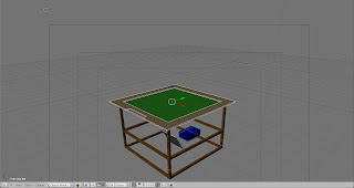
You can't tell in the picture above, but where the (currently) top piece of plywood hangs over, is where I put the other 2" frame and screwed it in. My final product, all set up, and flipped over, looked like this.


I can now officially make some tests!!! I got my webcam set up perfectly underneath the frame, and was able to power up all of the LEDs perfectly. This is an extremely old laptop, so a lot of the multi-touch software didn't work on it. The graphics card just isn't powerful enough. So, the best thing I ended up finding, and since this is just a test its okay, was MTmini. It's actually a really great application. For the final table though, I expect to be running linux.
Seth (cerupcat) posted about this application on the NUI forums and thats how I discovered it. You can find his post here. Under the old archived downloads, I downloaded the v1 software package. You can download that directly here. Setup was EXTREMELY simple. Though, this software package was designed to sense black blobs instead of white ones. This was a simple fix. If you go into the folder 'Touchlib_Tracking_Software' and edit config.xml. All you do is delete the line that says "". Once you've done this simply go back to the root folder and double click on '1) Calibration'.

Once it looks good click the escape key. Keep in mind these aren't the only settings you can adjust. You can also adjust the camera settings directly. After you're finished calibrating, go into the demos folder, then the c++ demos, and run smoke demo. Mine turned out great!

Also, here are some images directly from the webcam so you know how much you can do with software! Anyway, I'll go more in depth about software and everything else in a separate post. This was mainly just for test purposes, and because I was really excited to try it out after all that hard work! ;)


Works Sited:
The Comunity. NUI Group - Natural User Interface Group. Web. 21 June 2010. <http://nuigroup.com/>.


